Table of Contents
3. AERMET
With the output data from AERSURFACE, we can begin running AERMET.
3.1. Introduction
AERMET is a meteorological preprocessor used with the AERMOD air dispersion model. Its main function is to process surface and upper-air meteorological data to generate the necessary input files for AERMOD simulations. AERMET calculates key atmospheric parameters such as wind profiles, atmospheric stability, temperature gradients, and turbulence characteristics. These parameters are essential for accurately modeling how pollutants disperse in the atmosphere.
| Aspect | Details |
|---|---|
| Objective | Preprocess meteorological data for AERMOD, generating atmospheric profiles and planetary boundary layer (PBL) parameters. |
| Inputs | Surface data, upper-air sounding (radiosonde), and site characteristics (Surface roughness length (Zo), Albedo (Alb), and Bowen ratio (Bo)). |
| Outputs | • .SFC file - Processed surface data (10m wind, temperature, turbulence parameters) \ • .PFL file - Vertical atmospheric profiles (wind/temperature aloft, PBL height) |
3.2. Required Files for AERMET
3.2.1. AERMET Executable
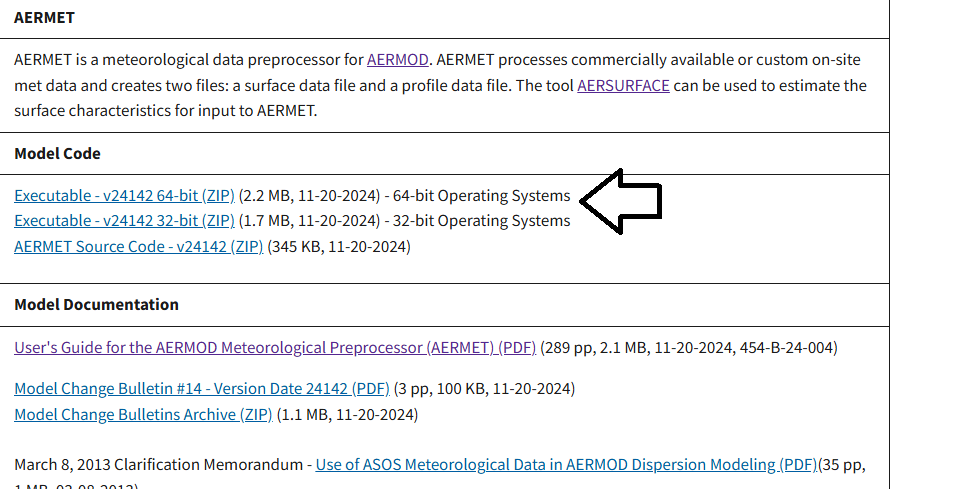
First, download the executable from the EPA AERMET website.
Navigate to the MODEL CODE section and click the executable compatible with your operating system version, as shown in Figure 1. Extract the downloaded file to the folder:
C:\Users\Cliente\Desktop\AermodTutorial\3.AERMET.
Figure 1
3.2.2. Surface Data
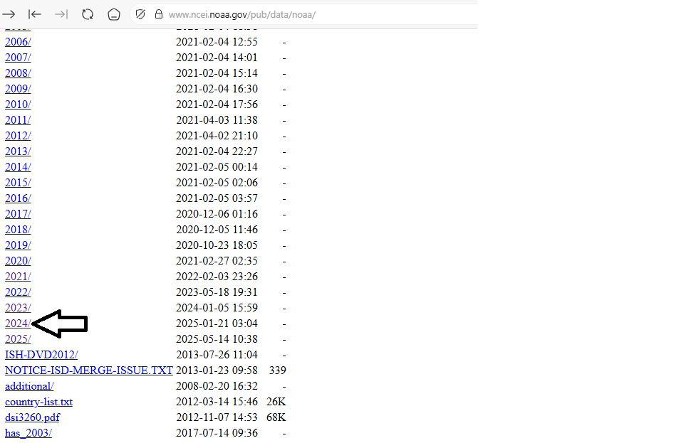
To download surface data, access the NOAA surface data website and navigate to the directory for the year 2024, as shown in Figure 2:
Figure 2
Now search for the file named 724397-54831-2024.gz (for the Central Illinois Regional Airport station), download it, and extract it to the folder:
C:\Users\Cliente\Desktop\AermodTutorial\3.AERMET.
Finally, rename the file to 724397-54831-2024.dat, create a subfolder named Surface_data, and move the file there, as shown in Figure 3:
Figure 3
3.2.3. Upper Air Data
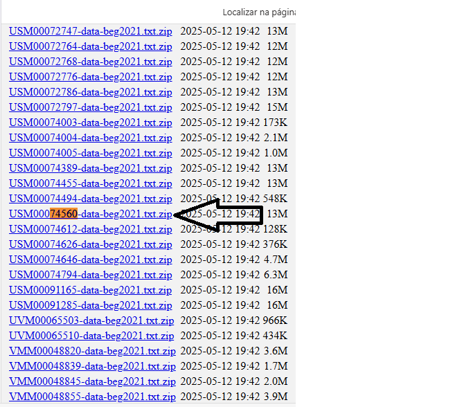
Lastly, download the radiosonde data from the radiosonde archive, searching for the station USM00074560-data (for Lincoln, IL, the closest radiosonde station to Bloomington).
Download the file as shown in Figure 4, and extract it to:
C:\Users\Cliente\Desktop\AermodTutorial\3.AERMET.
Figure 4
Rename the file to USM, create a new subfolder named Upper_Air_data, and move the file there (C:\Users\Cliente\Desktop\AermodTutorial\3.AERMET\Upper_Air_data), as shown in Figure 5:
Figure 5
3.3. Configuring AERMET
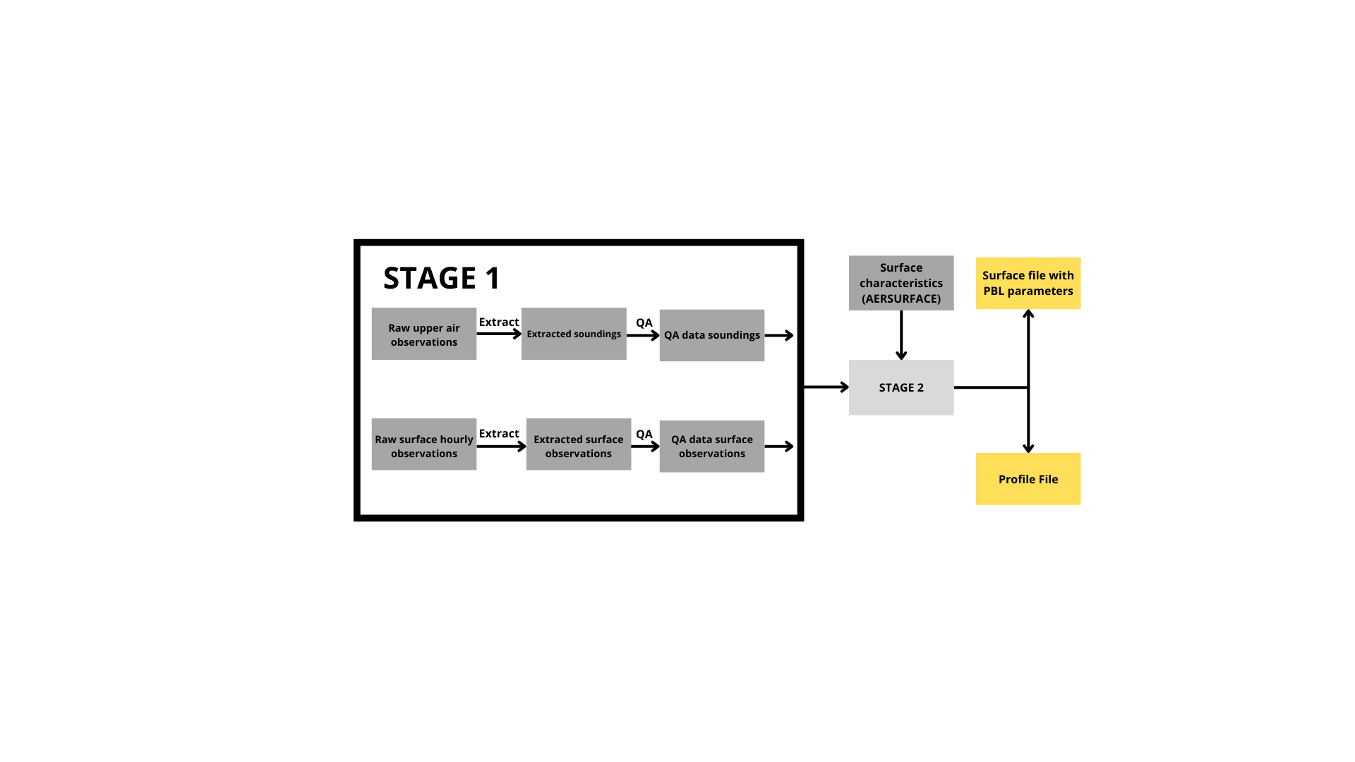
Now that all required input data is ready, we will split the processing into two stages:
- Stage 1: Extracts surface and upper-air data from archived formats and performs quality control.
- Stage 2: Processes Stage 1 outputs to calculate boundary layer parameters for AERMOD.
The workflow is illustrated in Figure 6:
Figure 6
3.3.1. AERMET STAGE 1
Create a text file named aermet_STG1.txt in C:\Users\Cliente\Desktop\AermodTutorial\3.AERMET with the following content:
 ** Stage 1 job messages msgSTG1.mes report msgSTG1.rpt
upperair
** Upper air data for Bloomington, IL
data .\Upper_Air_data\USM.txt IGRA
extract upper.iqa
location 00074560 40.15N 89.33W 5 179.2
xdates 2024/1/1 to 2024/1/2
qaout upper.oqa

surface
** Surface data for Central IL, Bloomington/Normal
data .\Surface_data\724397-54831-2024.dat ISHD
extract surface.iqa
qaout surface.oqa
location 54831 40.66N 89.69W 5
xdates 2024/1/1 to 2024/1/2
3.3.1.1. Stage 1 AERMET Configuration
JOB Section
| Line | Description |
| messages m1.mes | Log file storing processing messages |
| report m1.rpt | Detailed report file with processing results |
UPPERAIR Section
| Line | Description |
| data .\Upper_Air_data\USM.txt IGRA | Path to raw radiosonde data in IGRA format |
| extract upper.iqa | Output file with extracted data (pre-QA) |
| location 00074560 40.15N 89.33W 5 179.2 | Station details: \ • Code: 00074560 \ • Coordinates: 40.15N 89.33W \ • Anemometer height: 5m \ • Terrain elevation: 179.2m |
| xdates 2024/1/1 to 2024/12/31 | Processing period (full year) |
| qaout upper.oqa | Final post-QA output file |
SURFACE Section
| Line | Description |
| data .\Surface_data\724397-54831-2024.dat ISHD | Surface data in ISHD format (Integrated Surface Hourly Data) |
| extract surface.iqa | Extracted data before QA |
| qaout surface.oqa | Validated data ready for use |
| location 54831 40.66N 89.69W 5 | Station details: \ • WBAN code: 54831 \ • Coordinates: 40.66N 89.69W \ • Measurement height: 5m |
| xdates 2024/1/1 to 2024/12/31 | Time window matching upper-air data |
3.3.2. AERMET STAGE 2
Create another text file named aermet_STG2.txt in the same folder with:
 ** Stage 2 JOB MESSAGES mcr_st2.mes REPORT mcr_st2.rpt
UPPERAIR
QAOUT upper.oqa

SURFACE
QAOUT surface.oqa

METPREP
OUTPUT METAR.SFC
PROFILE METAR.PFL
LOCATION 000001 40.47N 88.97W 0
METHOD REFLEVEL SUBNWS
METHOD WIND_DIR RANDOM
NWS_HGT WIND 6.1
AERSURF BL_2024_Imp_Can.sfc
3.3.2.1. Stage 2 AERMET Configuration
METPREP Section
| Line | Description |
| OUTPUT METAR.SFC | Processed surface data output file |
| PROFILE METAR.PFL | Processed vertical profiles output file |
| LOCATION 000001 40.47N 88.97W 0 | Site details: \ • Code: 000001 \ • Coordinates: 40.47N 88.97W \ • Reference height: 0m |
| METHOD REFLEVEL SUBNWS | Reference height method (NWS standard) |
| METHOD WIND_DIR RANDOM | Wind direction handling for missing data (random imputation) |
| NWS_HGT WIND 6.1 | NWS standard wind measurement height (6.1m) |
| AERSURF BL_2024_Imp_Can.sfc | Surface characteristics file from AERSURFACE |
3.4 Running AERMET
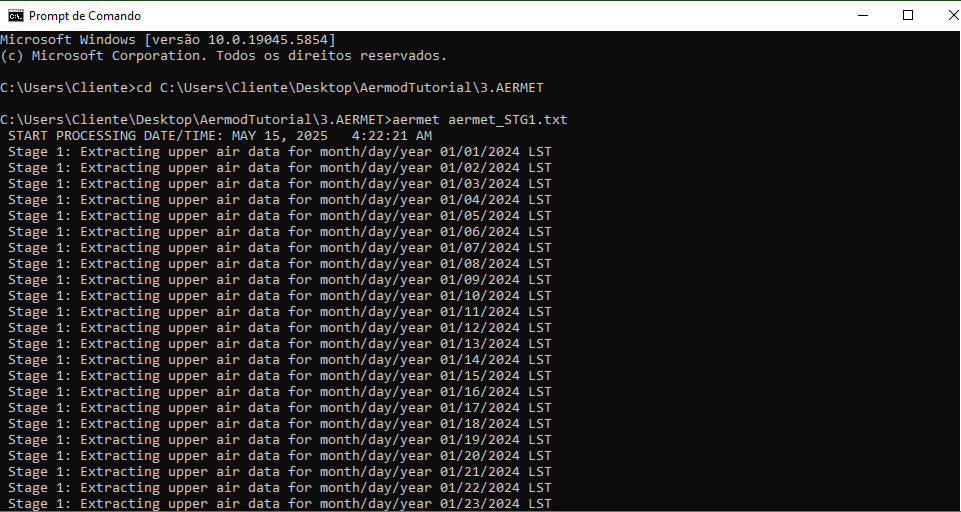
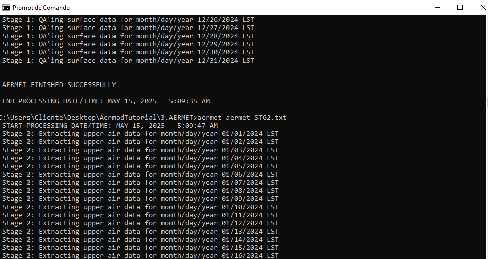
Open Command Prompt and run:
Figure 8
Figure 9
What is next?
With this completed, we can proceed to AERMAP, which is the last processor before moving on to AERMOD.
Attachment Here you can download the folder I used to create this document. It is important that you use it only for comparison purposes or in case you are unable to make progress on the project. Attached: aermet.rar

